If you’re a generator owner, you’ll have to test the windings sooner or later. Depending on your testing equipment and expertise, there are a few different ways to do this. In this blog post, we’ll discuss how to test generator windings and the different methods and help you choose the best way for you to test your windings.
As a safety precaution, it is important to test the windings of a generator before using it. This can be done with a simple multimeter. By setting the multimeter to continuity mode and touching the probes to each end of the winding, you can determine whether or not there is a continuous circuit.
If there is no continuity, then the winding is likely to open and should not be used. If there is continuity, then the winding is likely good, and you can proceed to use the generator.
What Is Generator Windings?
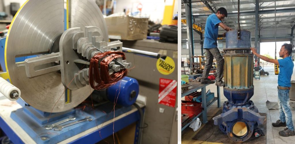
Generator windings are the coils of wire that make up the electromagnet within the generator. These coils are usually made from copper or aluminum. The movement of these coils creates the electricity produced by the generator through a magnetic field.
If you have ever seen a generator being used, you may have noticed that the windings are often located inside the generator’s housing. This is because the windings need to be protected from the elements. Generator windings can become damaged if they are exposed to moisture, dust, or other debris.
The windings inside a generator can be damaged by heat. If they get too hot, they can become brittle and break. To prevent this, it is important to keep the windings clean and free of debris.
If the wires inside your generator are damaged, it might not work as well or might not work at all. A qualified technician can test the wires to see if they are damaged.
Types of Generator Windings:
There are two types of generator windings: armature windings and field windings.
Armature Windings:
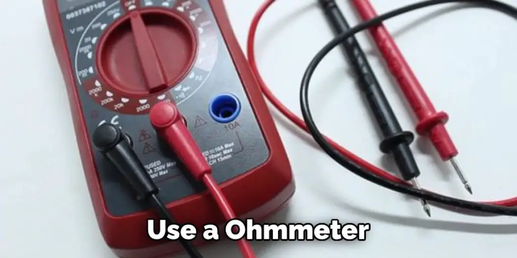
The armature is the rotating part of the generator, while the field winding is stationary. To test the armature winding of a generator, first, disconnect all load from the generator. Then, open the access door to the generator and visually inspect the winding for any damage. Next, use an ohmmeter to measure the resistance of the armature winding. If the resistance is not within specifications, then the armature winding must be replaced.
Field Windings:
To test the generator’s field winding, first disconnect all load from the generator. Then, open the access door to the generator and visually inspect the winding for any damage. Next, use an ohmmeter to measure the resistance of the field winding. If the resistance is not within specifications, then the field winding must be replaced.
Step by Step Process on How to Test Generator Windings:
Step 1. Isolate the Winding.
To ensure an accurate reading, you must first isolate the winding being tested from the rest of the generator. This is typically done by opening the generator’s main disconnect and removing all lead wires connected to the winding.
If you’re testing a winding that’s part of a bigger machine, like a stator, you’ll need to take it out of the machine first. Be careful to discharge any electricity from the winding before you remove it, so you don’t get hurt. Once it’s out, you’ll need to figure out which parts are the terminals. There are three common types of generator windings: star (wye), delta, and zigzag.
The difference between star and delta windings is that star windings have one end connected to the ground, while delta and zigzag windings do not. If you are unsure which type of winding you are dealing with, consult the manufacturer’s documentation or an experienced electrician.
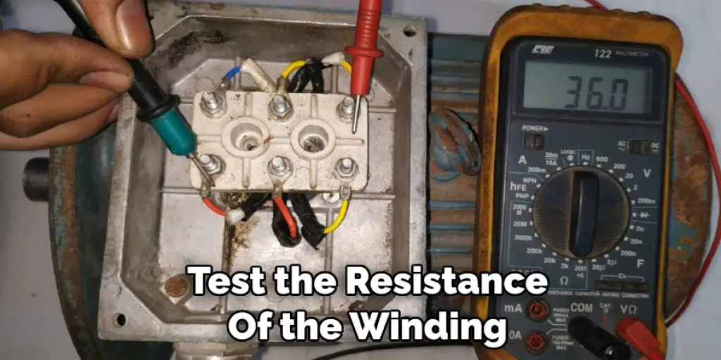
Step 2. Test the Resistance of the Winding.
The second step in testing a generator winding is to measure its resistance. Again, using a digital multimeter set to the ohms (Ω) scale can be done. To take an accurate reading, you must first ensure that the multimeter probes are making good contact with the winding terminals.
Once the probes are in place, note the reading on the multimeter display. If it is within the manufacturer’s specified range, the winding is said to have low resistance and is considered healthy. On the other hand, a high reading indicates that the winding has a high resistance and may be damaged.
Step 3. Check the Insulation of the Winding.
The third step in testing a generator winding is to check the insulation. This is done by measuring the resistance between the winding and the ground. The insulation should be high enough so that there is no significant current flowing through it. If the insulation is damaged, it will need to be repaired or replaced.
Another way to check the insulation is with a megger. This is an instrument that sends a high voltage through the winding and measures the resistance. Again, the insulation should be high enough to have no current flowing through it.

Step 4. Continuity Test of the Winding.
To check the continuity of the winding, use a multimeter in the resistance mode. Connect one lead of the multimeter to one end of the winding and the other lead to the other end. The multimeter will show a low resistance value (usually below 1 ohm) if there is continuity. Conversely, if there is no continuity, the multimeter will show an “open” or “infinite” resistance value. If you get an open reading, this indicates a break in the winding, and the generator will need to be repaired or replaced.
If you don’t have a multimeter, you can also do a continuity test with a battery and a bulb. To do this, connect one lead of the battery to one end of the winding and the other lead of the battery to one lead of the bulb. Then, touch the other lead of the bulb to the other end of the winding. Again, if there is continuity, the bulb will light up.
You Can Also Check It Out to Connect a Generator to a Solar System
Step 5. Polarity Test of the Winding.
This is an important test and must be carried out with great care. The least mistake made during the winding will result in a wrong reading. If you are in doubt as to the correctness of the readings, repeat the test. Do not attempt to interpret the results yourself but seek the help of a qualified person.
The object of this test is to determine the relative position of the armature winding with respect to the field winding. The phasing of these two windings will give the direction of rotation of the armature when power is applied.
The test is done by applying a DC voltage through a rheostat across the armature terminals and measuring the resulting amperage. The voltage is then reversed, and the amperage measurement is made again. By comparing the two amperages, the direction of rotation can be determined.
Step 6. No-Load Test of the Winding:
This test is conducted to determine the generator’s magnetizing current and excitation voltage. To conduct this test, first, disconnect the load from the winding. Then, apply a DC voltage to the winding and measure the resulting amperage.
The voltage that is required to produce a given amperage is known as the excitation voltage. The magnetizing current is the amperage that is flowing through the wind when there is no load on it. The no-load test can also be conducted with an AC power source. In this case, the RMS value of the voltage and current are measured.
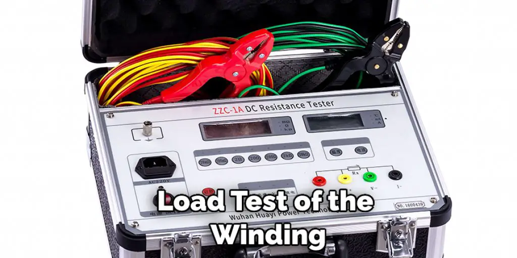
Step 7. Load Test of the Winding:
Now that your winding is isolated and powered, it is time to load test it. This will give you an idea of the health of your winding. A good way to load test a generator winding is by using a resistor bank.
If you do not have a resistor bank, you can use a large inductor or capacitor as your load. If you use an inductor, you will need to make sure that it is able to dissipate the heat that is generated. You can also use a variable frequency drive (VFD) as your load. A VFD will allow you to control the amount of power that is being drawn by the winding.
Tips and Warning on How to Test Generator Windings:
Tips:
- Read the manufacturer’s instructions carefully before testing the generator windings.
- Make sure that all of the generator’s parts are in good working order before testing the windings.
- Test the generator under different load conditions to get accurate results.
- Use a high-quality multimeter when testing the generator windings.
Warnings:
- Do not touch the generator’s windings while the generator is running.
- Be careful not to damage the generator’s windings when testing them.
- Always wear safety goggles and gloves when working with or around generators.
- Never operate a generator without proper ventilation.
Conclusion
Introduction: Generator windings are an important part of the generator. They need to be tested regularly to make sure they are in good condition and working properly. In this blog post, we will discuss how to test generator windings. The first way to test the windings is by measuring resistance with a multimeter.
The second way to test the windings is by using a merger. By following these methods, you can test the condition of your generator’s windings and ensure that they are working properly.


